🤫 Unlocking secret ThinkPad functionality for emulating USB devices
🤫 Unlocking secret ThinkPad functionality for emulating USB devices
This is the story of how I figured out a way to turn my ThinkPad X1 Carbon 6th Gen laptop into a programmable USB device by enabling the xDCI controller.
As a result, the laptop can now be used to emulate arbitrary USB devices such as keyboards or storage drives. Or to fuzz USB hosts with the help of Raw Gadget and syzkaller. Or to even run Facedancer with the help of the Raw Gadget–based backend. And do all this without any external hardware.
The journey of enabling xDCI included fiddling with Linux kernel drivers, xHCI, DWC3, ACPI, BIOS/UEFI, Boot Guard, TPM, NVRAM, PCH, PMC, PSF, IOSF, and P2SB, and making a custom USB cable 😱
⬅ Note the interactive table of contents on the left.
🎬 Introduction
One day, I was working on improving Raw Gadget.
Raw Gadget and UDCs. Raw Gadget is a Linux kernel module for emulating highly customizable USB devices. This module provides a userspace API for the Linux kernel USB Gadget subsystem. The flexibility of the API allows using Raw Gadget for fuzzing and exploiting USB hosts by providing malformed USB descriptors.
UDCs are also sometimes called USB Peripheral Controllers.
To emulate USB devices through the Gadget subsystem of the Linux kernel, one needs a special hardware component called the USB Device Controller (UDC). Such components are generally not present on PCs (right? 😉) but are typically embedded into single-board computers like a Raspberry Pi.
Raspberry Pi. Thus, I usually used a Raspberry Pi to work with Raw Gadget. However, dealing with a Raspberry Pi is a hassle: plugging in the wires, booting the board, accessing the shell, etc. So, for a while, I dreamt how nice it would be to have a UDC connected directly to my laptop instead.
EC3380-AB. At some point, I managed to find a solution for connecting a UDC to a PC: EC3380-AB.
Quite a pity modern laptops moved away from using ExpressCard 😢
EC3380-AB is an ExpressCard board based on the USB 3380 Peripheral Controller chip that implements a UDC. With the help of the Sonnet Echo ExpressCard-to-Thunderbolt adapter, EC3380-AB can be plugged into a Thunderbolt port to connect the UDC to a PC without an ExpressCard slot.

There are also a few other UDC boards based on USB 3380. But those connect over PCIe and thus require a bulky PCIe-to-Thunderbolt enclosure to connect them conveniently.
Two of these boards, USB3380EVB and PP3380-AB, might be familiar to those who worked with DMA attacks. Like EC3380-AB, these boards are powered by USB 3380 and are originally intended to serve as UDCs. However, they can also be reprogrammed to be used as a tool for DMA attacks over PCIe.
Working with EC3380-AB.
The combination of EC3380-AB and the Sonnet Echo adapter worked mostly fine.
However, the net2280 Linux kernel driver used for this UDC would sometimes glitch out.
Thus, occasionally, I had to replug the controller into my laptop to reset the driver state.
As I was plugging and unplugging EC3380-AB, I would check the contents of /sys/class/udc/ to make sure that EC3380-AB connected successfully.
This directory displays the UDCs connected to the system:
$ ls /sys/class/udc/
0000:0a:00.0
$ cat /sys/class/udc/0000\:0a\:00.0/uevent
USB_UDC_NAME=net2280
Huh.
At some point, I typed ls /sys/class/u in the terminal and pressed Tab to let it autocomplete to .../udc.
However, the autocomplete showed me another directory: /sys/class/usb_role.
Moreover, this directory unexpectedly contained another one named intel_xhci_usb_sw-role-switch.
“Hm, what the hell is this?” thought I 🤔
xHCI (eXtensible Host Controller Interface) is a USB HCD (Host Controller Device) used on x86-powered systems. It’s a hardware component that allows the system to act as a USB host.
/sys/class/usb_role is an interface for switching the hardware USB component between the host and the device modes.
Some computers use the same chip to serve either as an HCD or a UDC, depending on the chosen configuration, and this interface allows reconfiguring that in runtime.
xHCI role switch.
What surprised me here was seeing a usb_role switch for the xHCI device on my ThinkPad laptop.
I wouldn’t be surprised to see it on an x86-powered single-board computer or on an Intel NUC device.
But ThinkPad?
I thought it didn’t have any capability of being a USB device.
This was unexpected.
Out of curiosity, I tried writing device to intel_xhci_usb_sw-role-switch/role, which is supposed to switch the USB component on the laptop to the device mode.
But nothing happened: no dmesg messages, no new files in /sys/class/udc/.
So I decided to dig deeper.
🧐 Investigation
🐧 Reading kernel code
I started by looking into how intel_xhci_usb_sw-role-switch ended up appearing on my ThinkPad in the first place.
xHCI role switch implementation.
A grep for intel_xhci_usb_sw through the Linux kernel code yielded two results:
-
The
drivers/usb/roles/intel-xhci-usb-role-switch.cfile that contained the platform driver for anintel_xhci_usb_swdevice.This driver registered a USB Role Switch, which implemented the handlers for when
deviceorhostis written intointel_xhci_usb_sw-role-switch. Both handlers appeared to manipulate the registers of the xHCI device. -
The
drivers/usb/host/xhci-ext-caps.cfile that created theintel_xhci_usb_swvirtual platform device, for which the driver from #1 got registered.This device was only created when the xHCI driver set the
XHCI_INTEL_USB_ROLE_SWquirk flag. And this only happened for PCIe devices with a few specific device numbers. The list of numbers includedPCI_DEVICE_ID_INTEL_SUNRISEPOINT_LP_XHCIwith the value0x9d2f, which matched the xHCI PCIe device ID on my laptop.
ThinkPad. So apparently, the xHCI device on my laptop did support the role switching. Or at least its driver believed so.
Now the question was: What exactly happened when the driver wrote to the xHCI registers?
Did these writes produce any effects?
Or did the hardware not support the device role at all?
🔍 Searching online
The next thing I tried was looking online for references to intel_xhci_usb_sw-role-switch.
Mailing list discussion. This led me to the discussion titled Any example of USB gadget for DRD device mode on Intel Gemini Lake? on the Linux kernel mailing list. There, Dmitry Mikushin was facing the same issue as me: role switching for the xHCI device did not appear to work.
Dmitry’s question also noted that after switching the role, one of the ports was successfully recognized as a new USB device when connected with a cable to another laptop. However, initially, I managed to overlook this part of the question.
DWC3. Luckily, Heikki Krogerus came to the help:
| « |
So, do you have the DWC3 (the USB device controller) PCI device available/visible on your system?
What do you get if you run lspci -nn | grep USB?
The DWC3 PCI device ID on Gemini Lake is 0x31aa (search PCI_DEVICE_ID_INTEL_GLK in drivers/usb/dwc3/dwc3-pci.c).
|
|---|
DWC3 stands for the DesignWare Core SuperSpeed USB 3.0 Controller. This is an IP core (aka IP block or IP unit) provided by Synopsys that implements a UDC. Many vendors, including Intel, use this IP core in their systems.
In the response, Heikki suggested checking if a DWC3 UDC was present in the list of PCI devices. This made sense: if a UDC is present on a system, it has to be somehow connected. And it looked like Intel connected their DWC3 UDCs over PCI or PCIe.
Dmitry responded:
| « |
Yes, AFAIK, PCI_DEVICE_ID_INTEL_GLK_XHCI is actually 0x31a8, and I do have it:
00:15.0 USB controller [0c03]: Intel Corporation Device [8086:31a8] (rev 03).
|
|---|
Mux. Heikki answered:
| « | That is the xHCI controller, and it is not what you need if you want to use the connector in device mode. The xHCI and DWC3 IPs are separate IPs on GLK. That is why there is a mux between the two. |
|---|
Here, Heikki pointed out that xHCI and DWC3 UDC were different devices. And having xHCI enabled did not imply that the DWC3 UDC could be used.
Heikki also gave another valuable piece of information: there is a mux (multiplexer — a kind of switch) between xHCI and the DWC3 UDC.
And, apparently, changing the USB role via intel_xhci_usb_sw-role-switch should switch this mux.
Oh no. Heikki then continued:
| « |
The DWC3 USB Device Controller has device ID 31aa, so you want to see a PCI device with this device ID.
It’s not there.
So, the DWC3 PCI device is not enabled on your board, which means you do not have a USB Device Controller to deal with.
The connector is in host mode only. Sorry.
|
|---|
So, if the DWC3 UDC itself was not there, having the mux switched was pointless. Most likely, this is what was happening in my case.
xDCI in BIOS. Heikki then also added:
| « | If you can enter the BIOS menu, then you can try to find a setting named xDCI (so that’s “xDCI”, not “xHCI”). It is usually somewhere under some USB menu. If you have that, then enable it, and you should see the DWC3 PCI device in the operating system. |
|---|
This was where I encountered the term xDCI for the first time.
An online search for xDCI revealed:
| « | Extensible Device Controller Interface (xDCI) is an interface specification that defines Device Controller for a Universal Serial Bus (USB 3), which is capable of interfacing with USB 1.x, 2.0, and 3.x compatible devices. In the case that the computer is connected as a device to another computer (for example, a tablet connected to a desktop), then the xDCI controller will be activated inside the device and will talk to the Host on the other computer. |
|---|---|
| Extensible Device Controller Interface (xDCI), 12th Generation Intel® Core™ Processors Datasheet |
So, xDCI is what Intel calls its interface for the DWC3 UDC. Unlike xHCI, xDCI is the interface for the device side of USB, not the host one.
In the response, Heikki suggested checking whether xDCI could be enabled in BIOS. This created a spark of hope for me. Perhaps I could indeed enable xDCI in BIOS, and everything would work.
For simplicity, I will be using the term “xDCI” to refer to the Intel’s DWC3 UDC itself from now on.
Even though technically, the word “BIOS” refers to the legacy firmware used by older IBM PC–compatible systems, I will be saying “BIOS” to refer to the UEFI-compatible platform firmware of modern systems for simplicity.
Once I knew the term “xDCI”, I also did an online search for xHCI xDCI.
This led me to a diagram from the USB Virtualization documentation page of Project ACRN, which schematically shows xHCI, xDCI, and the mux between them.
xDCI in ACPI. In the discussion, Felipe Balbi, who was the maintainer for the USB Gadget subsystem in the Linux kernel up until recently, added:
| « |
Also, have a look at acpidump.
See if the device even exists in your DSDT but, perhaps, is disabled (look at the _STA method for OTDG or XDCI).
|
|---|
Here, Felipe proposed to also make sure that xDCI was enabled in ACPI.
| « | ACPI (Advanced Configuration and Power Interface) is an open standard that operating systems can use to discover and configure computer hardware components. ACPI defines hardware abstraction interfaces between the device’s firmware (e.g., BIOS, UEFI), the computer hardware components, and the operating systems. |
|---|---|
| ACPI, Wikipedia |
After reading more about ACPI, I found out that _STA method is used to check the device status.
The OS will only try to connect the device if its status indicates that the device is enabled and properly configured.
If the _STA method is not defined in ACPI at all, the device will not function.
Next steps. Finding this discussion was extremely helpful. Now I knew what to do next:
- Check if the xDCI device shows up in the list of PCIe devices;
- If not, check if there is a way to enable xDCI through BIOS;
- Finally, check if ACPI enables xDCI.
🚧 Checking PCIe and ACPI
Checking PCIe device.
Following Heikki’s guidance, I first checked whether the xDCI device appeared on my laptop’s list of PCIe devices via sudo lspci -vvnnn.
The only USB device that I saw there was xHCI with the 9d2f device ID:
00:14.0 USB controller [0c03]: Intel Corporation Sunrise Point-LP USB 3.0 xHCI Controller [8086:9d2f] (rev 21) (prog-if 30 [XHCI])
	Subsystem: Lenovo Sunrise Point-LP USB 3.0 xHCI Controller [17aa:225c]
	Control: I/O- Mem+ BusMaster+ SpecCycle- MemWINV- VGASnoop- ParErr- Stepping- SERR- FastB2B- DisINTx+
	Status: Cap+ 66MHz- UDF- FastB2B+ ParErr- DEVSEL=medium >TAbort- <TAbort- <MAbort- >SERR- <PERR- INTx-
	Latency: 0
	Interrupt: pin A routed to IRQ 130
	Region 0: Memory at 2ffb210000 (64-bit, non-prefetchable) [size=64K]
	Capabilities: [70] Power Management version 2
		Flags: PMEClk- DSI- D1- D2- AuxCurrent=375mA PME(D0-,D1-,D2-,D3hot+,D3cold+)
		Status: D0 NoSoftRst+ PME-Enable- DSel=0 DScale=0 PME-
	Capabilities: [80] MSI: Enable+ Count=1/8 Maskable- 64bit+
		Address: 00000000fee00358  Data: 0000
	Kernel driver in use: xhci_hcd
	Kernel modules: xhci_pci
Then, I checked the dwc3 driver source code to find out what ID the xDCI device should have:
SPTLP stands for “Sunrise Point-LP”.
#define PCI_DEVICE_ID_INTEL_SPTLP 0x9d30
Unfortunately, I could not see a device with this ID 😢
However, from the lspci output, I found out that my ThinkPad X1 Carbon 6th Gen laptop uses the Sunrise Point-LP chipset.
This information came in handy later.
Checking ACPI.
Before moving on to checking BIOS settings, I decided to find out whether the _STA method existed in ACPI for XDCI or OTGD.
I dumped and decompiled DSDT via:
$ sudo apt-get install acpica-tools
$ sudo acpidump > acpi.dat
$ acpixtract -a acpi.dat
$ iasl -d dsdt.dat
And grepped dsdt.dsl for XDCI:
Device (XDCI)
{
    Name (_ADR, 0x00140001)  // _ADR: Address
    OperationRegion (OTGD, PCI_Config, 0x00, 0x0100)
    Field (OTGD, DWordAcc, NoLock, Preserve)
    {
        DVID,   16,
        Offset (0x10),
        XDCB,   64
    }

    Method (_STA, 0, NotSerialized)  // _STA: Status
    {
        If ((DVID != 0xFFFFFFFF))
        {
            Return (0x0F)
        }
        Else
        {
            Return (0x00)
        }
    }

    ...
}
This was good news: the _STA method was present!
While this didn’t necessarily mean that ACPI properly set up xDCI, this was already promising.
I believe that DVID in the _STA implementation stands for “Device ID”, and it is read from the PCIe Configuration Space of the xDCI device, but I didn’t analyze ACPI for xDCI beyond that.
Status result.
Out of curiosity, I decided to check what the _STA method returned.
After looking around /sys/bus/acpi/devices/, I found out that device:33 was designated to the XDCI ACPI device:
$ cat /sys/bus/acpi/devices/device:33/path
\_SB_.PCI0.XDCI
And the result of the _STA method was:
$ cat /sys/bus/acpi/devices/device:33/status
15
Interestingly, _STA returned 15, which stands for the device being enabled and functioning.
However, as I had no xDCI device show up in lspci, this was clearly false.
Perhaps everything functioned properly only from the ACPI point of view.
I decided that finding a defined _STA method was good enough and proceeded to check BIOS.
🎁 Checking BIOS
An online search for combinations of ThinkPad, BIOS, and xDCI yielded no relevant results.
Apparently, no one has attempted to figure out whether xDCI can be enabled in Thinkpad BIOS.
BIOS settings. I booted into the BIOS settings screen (aka BIOS Setup) and looked around for something related to xDCI or OTG. I found nothing.
I knew that many Lenovo laptops had a hidden Advanced page in their BIOS settings.
So, perhaps I could find the xDCI setting there.
While some Lenovo laptops allow unlocking this page via magic keypresses, I failed to find a way to do this on Thinkpad X1 Carbon.
But maybe there was another way.
Unpacking BIOS.
Before trying to unlock the Advanced page, I decided to check the BIOS image directly for the presence of an xDCI-related setting.
I downloaded the BIOS Bootable CD update image from the Lenovo website, unpacked it, and mounted it:
$ sudo apt-get install genisoimage
$ geteltorito -o n23ur39w.img n23ur39w.iso
$ sudo kpartx -av ./n23ur39w.img
$ sudo mkdir /mnt/bios
$ sudo mount -o ro /dev/mapper/loop0p1 /mnt/bios/
The main BIOS binary was now in /mnt/bios/FLASH/N23ET86W/\$0AN2300.FL1.
For reference, here’s how to unmount the image later:
$ sudo umount /mnt/bios/
$ sudo kpartx -d ./n23ur39w.img
Also, for reference, here’s how to extract BIOS from the .exe update finary that Lenovo provides:
$ sudo apt-get install innoextract
$ innoextract n23uj39w_v2.exe
$ ls codeGetExtractPath/N23ET86W/\$0AN2300.FL1
Right in the middle of me meddling with BIOS images, Lenovo removed its Linux *.cab BIOS update packages from their website 🤔
So no more cabextract 😢
Come to think of this, new ThinkPads are also missing Linux kernel drivers for their MIPI web cameras.
Eh, Lenovo.
UEFITool. I installed UEFITool and imported the BIOS binary:
$ sudo apt-get install uefitool
$ UEFITool /mnt/bios/FLASH/N23ET86W/\$0AN2300.FL1
I searched for xDCI and got a hit in GUID E6A7A1CE-5881-4B49-80BE-69C91811685C, corresponding to the Setup module.

| « | A GUID is a unique 128-bit number that is a Globally Unique IDentifier. Each time an image, protocol, device, or other item is defined in UEFI, a GUID must be generated for that item. |
|---|---|
| GUIDs, EDK II Driver Writer’s Guide |
I extracted the binary data from the PE32 image section of the Setup module into Setup.bin via Extract body... from UEFITool and checked for strings that contained xDCI:
$ strings -el ./Setup.bin | grep xDCI
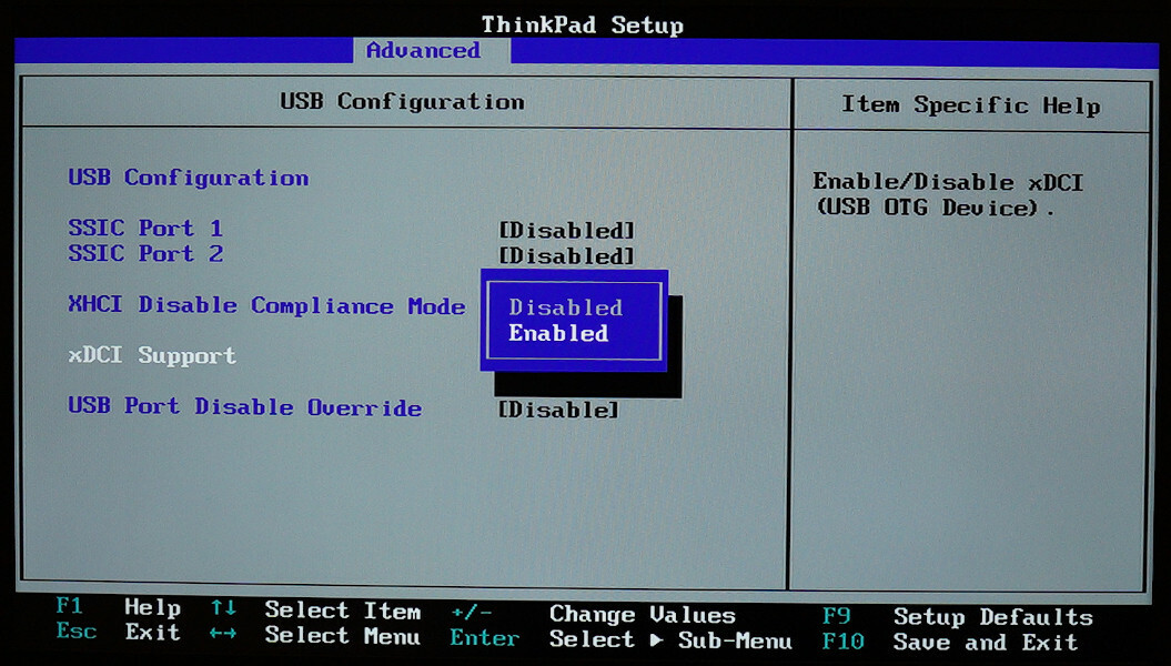
xDCI Support
Enable/Disable xDCI (USB OTG Device).
Aha! So, the setting for enabling xDCI was there; it was just indeed hidden by default.
💡 Enabling xDCI
At this point, I had high hopes that xDCI could be enabled through BIOS. I only had to find a way to unlock the setting to do this.
⚙ Enabling xDCI via Advanced settings
The first thing I tried was unlocking the hidden Advanced BIOS page.
Luckily, the BIOS modding community has already figured this out. The process is well-documented by the authors of the x1c6-hackintosh project coordinated by Tyler Nguyen. That project aims to run MacOS on ThinkPad X1 Carbon 6th Gen — specifically the laptop that I had.
SPI reflashing.
Unlocking the Advanced page via the proposed method required reflashing the SPI chip that stores BIOS.
The most common approach for reflashing the BIOS SPI chip is attaching a clip to the chip on the laptop’s motherboard and using an SPI programmer to rewrite the chip’s contents. The good thing about this approach is that you can attach the clip once and then reflash BIOS as many times as you’d like.
However, I was hesitant to use that approach. A few years ago, I successfully fried the motherboard on another laptop when I tried reflashing BIOS with an SPI clip. I guess I either connected the clip improperly, or the motherboard just didn’t tolerate the SPI chip being powered externally. This time, I wanted to avoid messing this up.
A safer approach to reflashing an SPI chip is to unsolder it from the motherboard and directly connect it to an SPI programmer. This is more time-consuming but allows avoiding damaging the motherboard. In the worst case, you would just kill the SPI chip, which is easily replaceable.
SPI socket. Instead of unsoldering and soldering the chip back on for each BIOS test, I decided to replace the SPI chip on the motherboard with an SPI socket. With the socket in place, I could take the chip out and put it back in whenever I wanted.
My soldering skills are not great. Luckily, Sergey Korablin, who used to design and assemble motherboards for a job, was around to help me with soldering 🤗
Accessing to the SPI chip on the ThinkPad X1 Carbon 6th Gen motherboard required removing the Wi-Fi antenna module. This module was held by a single screw, so this was not hard. We also disconnected the main laptop battery before soldering, just in case (and I also did that whenever I took the chip out of the socket).

Wieson G6179-10. For the SPI socket, I chose Wieson G6179-10 by Adafruit.
This socket had a few non-critical problems:
-
It was quite large, so the bottom laptop lid didn’t fully close;
-
The latch on the socket was tight, so opening it required care to avoid tearing it apart from the motherboard (I used a thread to pull on the latch while holding the socket in place);
-
The connection between the chip and the socket was flaky: my laptop would occasionally shut down and make beep noises on the power-on (I had to jiggle the chip in the socket to fix that temporarily).
But overall, the socket was good enough for running my experiments.
FT2232H Mini Module. For reflashing the SPI chip, I used the FTDI FT2232H Mini Module, which is a USB-to-serial converter that supports working with SPI, UART, I2C, and JTAG.
I learned about this module from an article by Dmytro Oleksiuk many years ago and have it in my toolkit since then.
For reference, here’s the pinout of this module for working with SPI chips:
The module can simultaneously work with two SPI chips through different channels (named 2 and 3).
| SPI chip pin | Boarn pin, ch. 2 | Board pin, ch. 3 |
|---|---|---|
| 1 | CN2.12 | CN3.23 |
| 2 | CN2.09 | CN3.24 |
| 3 | CN2.14 | CN3.21 |
| 4 | CN2.02 | CN3.04 |
| 5 | CN2.10 | CN3.25 |
| 6 | CN2.07 | CN3.26 |
| 7 | CN2.13 | CN3.20 |
| 8 | CN2.05 | CN3.01 |
To connect the SPI chip pins to the FT2232H module, I used a SOP8 to DIP8 adapter (similar to this one) and a bunch of jump wires.
I also connected CN2.1 to CN2.11 and CN3.1 to CN3.3 on the FT2232H module to enable the USB Bus-Powered mode according to the module’s datasheet.

To dump the contents of the SPI chip via the module, I used flashrom:
$ sudo flashrom -p ft2232_spi:type=2232H,port=A -r bios.bin
Tip: always dump SPI chips twice and make sure the contents in both dumps match.
Patching BIOS. The BIOS modding guide suggested patching the BIOS image in two steps:
-
Use the
UEFIPatchtool to apply a provided set of patches; -
Use a hex editor to change the
4C 4E 56 42 42 53 45 43 FBbyte sequence to4C 4E 56 42 42 53 45 43 FF(the last byte is different).
Before mindlessly following these steps, I decided to get at least a high-level understanding of what these changes did.
First patch.
After poking around, I found out that the first step replaced references to the GUID for the Date/Time BIOS page with such for the Advanced one:
# SystemFormBrowserCoreDxe | enable advance menu Lenovo xx70/xx80
721C8B66-426C-4E86-8E99-3457C46AB0B9 10 P:04320b483cc2e14abb16a73fadda475f:778b1d826d24964e8e103467d56ab1ba
32442D09-1D11-4E27-8AAB-90FE6ACB0489 10 P:04320b483cc2e14abb16a73fadda475f:778b1d826d24964e8e103467d56ab1ba
With this patch, the Date/Time BIOS settings page should be replaced with the Advanced one.
I applied the patch above via UEFIPatch to my bios.bin:
$ sudo apt-get install uefitool-cli
$ UEFIPatch bios.bin patch.txt -o bios-patched.bin
Second patch. The second step of changing a magical byte sequence was quite cryptic.
I suspect this patch switches the TPM-related BIOS setting bit in NVRAM, but I didn’t check it.
Eventually, I found out that this change was forcing the TPM (Trusted Platform Module) into the MFG Mode (Manufacturing Mode).
This prevented Boot Guard from detecting the BIOS modification from step #1.
| « | Intel Boot Guard is a processor feature that prevents the computer from running firmware (UEFI) images not released by the system manufacturer. When turned on, the processor verifies a digital signature contained in the firmware image before executing it using the public key, which is fused into the system’s Platform Controller Hub (PCH) by the system manufacturer (not by Intel). As a result, Intel Boot Guard makes it impossible for end users to install replacement firmware or modded BIOS. |
|---|---|
| Intel vPro, Wikipedia |
Normally, disabling Boot Guard should be much harder than simply flipping a bit in the BIOS binary. But I guess ThinkPad X1 Carbon 6th Gen is just old and vulnerable.
I did this step on a fairly old BIOS version 1.37. It is possible that this Boot Guard bypass has been fixed in one of the newer versions. However, the NVRAM approach I discuss below should still work.
I tried applying only the first change without the second. The laptop made beeping noises, most likely indicating a Boot Guard failure, and refused to boot.
To apply the patch from the second step, I simply used the ghex hex editor.
Flashing. After applying both patches, I flashed the modified BIOS to the SPI chip:
$ sudo flashrom -p ft2232_spi:type=2232H,port=A -w bios-patched.bin
And put the chip into the socket.
Advanced settings.
After booting into BIOS, the Date/Time page disappeared, but the Advanced page appeared instead, as expected 🥳
I haven’t found a way to take BIOS screenshots, so I had to take pictures of the screen 🙃
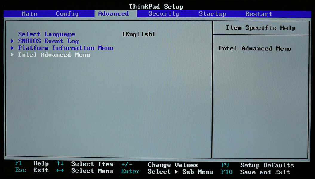
After following through Intel Advanced Menu, PCI-IO Configuration, and USB Configuration, I found the setting called xDCI Support and switched it to Enabled.
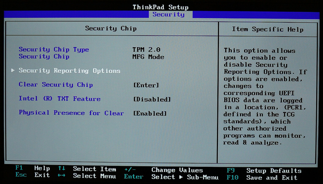
I also checked the TPM settings.
As expected, the TPM was switched to MFG Mode.
Success.
After I booted the laptop, I checked lspci once again.
Magically, the xDCI device with the expected 9d30 device ID appeared 🥳:
00:14.1 USB controller [0c03]: Intel Corporation Device [8086:9d30] (rev 21) (prog-if fe [USB Device])
	Subsystem: Lenovo Device [17aa:225c]
	Control: I/O- Mem+ BusMaster+ SpecCycle- MemWINV- VGASnoop- ParErr- Stepping- SERR- FastB2B- DisINTx-
	Status: Cap+ 66MHz- UDF- FastB2B- ParErr- DEVSEL=fast >TAbort- <TAbort- <MAbort- >SERR- <PERR- INTx-
	Latency: 0
	Interrupt: pin B routed to IRQ 17
	Region 0: Memory at 2ffb000000 (64-bit, non-prefetchable) [size=2M]
	Region 2: Memory at 2ffb230000 (64-bit, non-prefetchable) [size=4K]
	Capabilities: [80] Power Management version 3
		Flags: PMEClk- DSI- D1- D2- AuxCurrent=0mA PME(D0+,D1-,D2-,D3hot+,D3cold-)
		Status: D0 NoSoftRst+ PME-Enable- DSel=0 DScale=0 PME-
	Capabilities: [90] Vendor Specific Information: Len=14 <?>
	Kernel driver in use: dwc3-pci
	Kernel modules: dwc3_pci
Moreover, the kernel even automatically loaded the dwc3 UDC driver (remember that xDCI is based on DWC3), and a new entry appeared in the list of UDC devices 🤯:
$ ls /sys/class/udc/
dwc3.1.auto
The only thing left was checking whether this UDC driver actually worked with xDCI.
Shortcomings. This approach of enabling xDCI had two shortcomings. It required:
-
Reflashing the SPI chip via a programmer. This sets a high bar for those wishing to enable xDCI on their machine. Doing this might also be impossible on newer systems due to RPMC; see the Afterword section.
-
Having a Boot Guard bypass. While there is a bypass for the X1 Carbon 6th Gen laptop, other machines might not be vulnerable in the same way.
I tried to tackle these problems later; see the sections below.
🧁 Checking xDCI
At this point, I had xDCI enabled in BIOS, and the dwc3 UDC driver was loaded.
As before, I switched the USB role to the device state:
$ echo device | sudo tee /sys/class/usb_role/intel_xchi_usb_sw-role-switch/role
And as before, nothing happened; no new dmesg messages appeared, at least.
But as I now had the UDC driver loaded, I could attempt emulating a USB device through it and check if that works.
Finding port. First, I had to figure out to which USB port xDCI was connected, if to any.
On Raspberry Pi–like boards, there is usually a single USB port that can be used for USB device emulation; such port is typically marked as “USB OTG”. But there are no such markings on ThinkPad laptops. Moreover, it could be that the xDCI-enabled port of the xHCI controller was not wired to the external casing of the laptop at all 😟
To find the xDCI-enabled port, I tried plugging in a USB flash drive into all external ports one by one while having the USB role set to device.
The second port I tried didn’t work: the OS did not detect the flash drive.
But once I switched the USB role back to host, the port started working.
So, it looked like I had found the right port 🥳

USB cable. Next, I needed a USB cable to connect my laptop to a USB host.
First, the cable had to be male-to-male: the xDCI-enabled port of my laptop was type A, not type B, which is typically used on USB devices. So, I needed a cable with a type A connector on both sides.
Technically, male-to-male cables are not compliant with USB 2.0. But, oh well, USB is weird.
Then, it was reasonable to use a cable with the power VBUS line disconnected.
It could be that role switching did not turn off the power on the xDCI-enabled port (and this was indeed the case: I later checked with a USB breakout board and a multimeter).
And connecting two devices with slightly different VBUS levels might not be a good idea.
A normal USB 2.0 cable has four wires inside: the power VBUS and the ground GND lines that the host uses to supply 5 V and up to 500 mA of power to the device, and the data D- and D+ lines that are used primarily to transmit data.
Making USB cable.
For the initial testing, I cut open two USB 2.0 cables with type A connectors and used them to make a single male-to-male cable with VBUS disconnected.
Later, I switched to using PortaPow USB Power Blocker with a male-to-male USB 2.0 cable as a more production-grade solution.
PortaPow USB Power Blocker is a USB adapter that disconnects VBUS while leaving the data D- and D+ and the ground GND lines untouched.
Perfect for my use case.
 disconnected;<br>Right: male-to-male USB 2.0 cable with PortaPow USB Power Block attached")
Right: male-to-male USB 2.0 cable with PortaPow USB Power Block attached
I also tried using the USB 3.0 Super-Speed A/A Debugging Cable made by DataPro.
This is a male-to-male USB 3.0 cable that leaves VBUS disconnected (along with USB 2.0 D- and D+) and swaps the SuperSpeed receiver/transmitter differentials pairs.
However, this cable didn’t work for my use case; I haven’t tried to figure out why.
Update from 11.06.2024: As pointed out by one of the readers, the DataPro cable didn’t work, as establishing a SuperSpeed connection requires establishing a High-Speed one first.
And the latter fails, as the DataPro cable disconnects USB 2.0 D- and D+.
Instead, using the LogiLink CU0038 cable with manually-cut VBUS wire worked perfectly for emulating SuperSpeed devices.
Gadget Zero.
Now came the moment of truth.
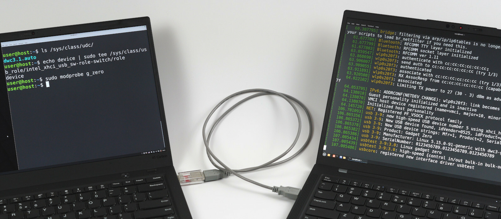
I connected the xDCI-enabled port of my X1 Carbon 6th Gen laptop to a USB port of another computer and loaded the g_zero gadget driver module.
g_zero is a gadget driver module that is typically used for testing UDCs.
Its configuration entry says: “Make this be the first driver you try using on top of any new USB peripheral controller driver”.
Once loaded, this module emulates a testing USB device through the first UDC it finds on the system.
And it worked! The g_zero gadget driver successfully emulated a USB device through xDCI for another laptop that I used as the host 🥳

Awesome! 😃
Before moving on to showing a few more interesting usage examples for xDCI, I’ll cover two other approaches to enabling it that I tried.
🧾 Attempting to enable xDCI via PCH
After I managed to enable xDCI by reflashing the SPI chip, I was wondering whether it would be possible to do this purely via software. My thinking was that since BIOS somehow enabled xDCI, perhaps I could do the same from the booted OS.
For this, I had to figure out how exactly BIOS enabled xDCI.
This approach was suggested to me by Maxim Goryachy, who is an expert in the low-level platform security area. Maxim also tremendously helped me by answering questions about BIOS and PCH.
For everything in this section, I used the old BIOS version 1.37. I did not check whether it all works the same with newer versions.
BIOS source. I’m not a big fan of reverse engineering binaries, so decompiling BIOS to understand how it handled xDCI was not a thing I wanted to do.
Luckily, there have been several BIOS source code leaks from various manufacturers over the last few years. Thus, obtaining the source code for the Kaby Lake BIOS was not hard (my ThinkPad X1 Carbon 6th Gen laptop with the i7-8650U CPU is based on the Kaby Lake R architecture).
I will not provide a link to the leaked source code nor full snippets of non-public code to limit the possibility of violating some copyrights.
But you can find the leaked code yourself if you’re interested; search for KabylakeSiliconPkg.
xDCI in BIOS.
I grepped the BIOS source code for xDCI and found the code responsible for its bring-up in Pch/Library/Private/PeiPchInitLib/PchXdci.c.
The code was roughly structured like this:
ConfigureXdci() {
	// Do stuff.

	if (XdciConfig.Enable == 0) {
		// Do stuff to disable xDCI.

		// Disable xDCI in PSF.

		// Disable xDCI in PMC.
	} else {
		// Do stuff to enable xDCI.
	}
}
The parts of the code that I replaced with comments appeared to manipulate various PCH registers.
| « | Platform Controller Hub (PCH) is a family of Intel’s single-chip chipsets. PCH controls certain data paths and support functions used in conjunction with Intel CPUs. |
|---|---|
| Platform Controller Hub, Wikipedia |
My idea was to try reverting all of the register manipulations done in the disable branch in the reverse order and then apply the manipulations from the enable branch.
Datasheet. Before proceeding, I decided to try finding a datasheet for the PCH used on my laptop. The datasheet could hopefully describe the PCH registers, which would be helpful.
First, I found out that Sunrise Point (the chipset on my laptop) is the codename for the series 100 PCH chipsets. Even though Kaby Lake does support the 200 series chipsets, ThinkPad X1 Carbon 6th Gen used an older one.
After that, I managed to find the Intel 100 Series Chipset Family Platform Controller Hub (PCH) datasheet.
However, the datasheet subtitle said “Supporting S and H Platform Register Information”. Later, I discovered that this meant that this specific datasheet applied to Sunrise Point-H chipsets, not Sunrise Point-LP, which I had. But it was still good enough for my purposes.
🔋 Enabling xDCI in PMC
The last step in the branch responsible for disabling xDCI in BIOS was disabling it in PMC.
PMC (Power Management Controller) is a controller that manages power 🤓
Naturally, disabling xDCI in PMC most likely disconnected the xDCI device from power.
These register and bit offsets are public in tianocore/edk2-platforms.
xDCI in PMC.
To disable xDCI in PMC, BIOS set the B_PCH_PWRM_NST_PG_FDIS_1_XDCI_FDIS_PMC bit (#24) in the R_PCH_PWRM_NST_PG_FDIS_1 register (offset 0x628) of the PMC device.
I searched through the PCH datasheet and found out that NST_PG_FDIS_1 was one of the PMC Chipset Initialization Registers, and its bit #24 was responsible for XDCI Function Disable as expected.

PMC registers.
To enable xDCI in PMC, I thus wanted to reset the XDCI Function Disable bit in the NST_PG_FDIS_1 register of the PMC device.
The question then was: “How do I access this PMC register from the OS?”.
This turned out to be not hard.
In the datasheet, the NST_PG_FDIS_1 register was listed in the PMC Memory Mapped Registers section.
This meant that the register was memory-mapped, and thus, I could access it through a specific address in physical memory.
I only had to figure out what that address was.
PMC in BIOS. First, I checked how BIOS finds this address.
As it turned out, BIOS read the PMC memory-mapped register area address from the R_PCH_PMC_PWRM_BASE register (offset 0x48) within the PCIe Configuration Space of the PMC device:
This code is public in tianocore/edk2-platforms.
EFI_STATUS EFIAPI PchPwrmBaseGet (OUT UINT32 *Address)
{
  UINTN PmcBase = MmPciBase (
                    DEFAULT_PCI_BUS_NUMBER_PCH,
                    PCI_DEVICE_NUMBER_PCH_PMC,
                    PCI_FUNCTION_NUMBER_PCH_PMC
                  );
  *Address = MmioRead32 (PmcBase + R_PCH_PMC_PWRM_BASE) &
               B_PCH_PMC_PWRM_BASE_BAR;
  return EFI_SUCCESS;
}
Click the switch to see the full source code.
Note that the PMC PCIe Configuration Space area (PmcBase in the snippet above) differs from the PMC memory-mapped register area (denoted as PWRMBASE).
Both are technically memory-mapped (can be accessed through physical memory), but they serve different purposes and reside at different addresses.
PMC device. There indeed was a PMC PCIe device on my laptop:
00:1f.2 Memory controller [0580]: Intel Corporation Sunrise Point-LP PMC [8086:9d21] (rev 21)
        Subsystem: Lenovo Sunrise Point-LP PMC [17aa:225c]
        Control: I/O- Mem- BusMaster- SpecCycle- MemWINV- VGASnoop- ParErr- Stepping- SERR- FastB2B- DisINTx-
        Status: Cap- 66MHz- UDF- FastB2B- ParErr- DEVSEL=fast >TAbort- <TAbort- <MAbort- >SERR- <PERR- INTx-
        Region 0: Memory at ee420000 (32-bit, non-prefetchable) [disabled] [size=16K]
The device and function numbers 1f.2 matched PCI_DEVICE_NUMBER_PCH_PMC (31, which is 1f in hex) and PCI_FUNCTION_NUMBER_PCH_PMC (2) from the BIOS code.
The register offset and the PCIe device numbers also matched the information in the datasheet.

Thus, to change the value of the NST_PG_FDIS_1 register, I could read out the PMC memory-mapped register area address from R_PCH_PMC_PWRM_BASE and then overwrite the value at that address in physical memory.
However, I ended up using a different approach.
PMC in kernel. While looking into how to work with PMC registers, I also searched through the Linux kernel code to find out whether it interacted with PMC.
As it turned out, it did!
The kernel contained a global pointer to a pmc_core_device platform device:
static struct platform_device *pmc_core_device;
Whose driver data
contained a pointer to a pmc structure:
struct pmc {
	u64 base_addr;
	void __iomem *regbase;	/* Address of memory-mapped PMC reg. area. */
	const struct pmc_reg_map *map;
	u32 *lpm_req_regs;
};
Which contained a pointer to the PMC memory-mapped register area regbase, which, in turn, could be read or written via readl and writel:
static inline u32 pmc_core_reg_read(struct pmc *pmc, int reg_offset)
{
	return readl(pmc->regbase + reg_offset);
}

static inline void pmc_core_reg_write(struct pmc *pmc, int reg_offset,
				      u32 val)
{
	writel(val, pmc->regbase + reg_offset);
}
Thus, instead of reading out the address myself, I decided to reuse the mapping that the kernel provided.
Resetting bit.
I wrote a small kernel module that hijacks the PMC memory-mapped register area the kernel mapped and changes the NST_PG_FDIS_1 value:
#define SPT_PMC_NST_PG_FDIS_1_OFFSET	0x628
#define SPT_PMC_NST_PG_FDIS_1_BIT_XDCI	BIT(24)

static void enable_xdci_in_fdis_1(void)
{
	struct pmc *pmc = find_pmc();

	u32 reg_value = readl(pmc->regbase + SPT_PMC_NST_PG_FDIS_1_OFFSET);
	pr_err("xdci: NST_PG_FDIS_1 is %x\n", reg_value);
	int xdci_bit = !!(reg_value & SPT_PMC_NST_PG_FDIS_1_BIT_XDCI);
	pr_err("xdci: XDCI bit is %d\n", xdci_bit);

	reg_value &= ~SPT_PMC_NST_PG_FDIS_1_BIT_XDCI;
	pr_err("xdci: writing %x to NST_PG_FDIS_1\n", reg_value);
	writel(reg_value, pmc->regbase + SPT_PMC_NST_PG_FDIS_1_OFFSET);

	reg_value = readl(pmc->regbase + SPT_PMC_NST_PG_FDIS_1_OFFSET);
	pr_err("xdci: NST_PG_FDIS_1 is %x\n", reg_value);
}
Another reason I chose the kernel approach is that I was initially thinking about writing a kernel driver for enabling xDCI.
It should, however, be possible to access the PMC memory-mapped registers from userspace via /dev/mem without writing a kernel module.
Fail. Unfortunately, resetting the bit failed:
xdci: NST_PG_FDIS_1 is 3403ba8
xdci: XDCI bit is 1
xdci: writing 2403ba8 to NST_PG_FDIS_1
xdci: NST_PG_FDIS_1 is 3403ba8
The NST_PG_FDIS_1 value didn’t change after an overwrite attempt.
My guess at that point was that the register was locked. This is a typical case with configuration registers: they might be initially writeable, but then they might get locked during boot.
Register locked.
After searching through the PCH datasheet, I discovered that there was indeed a way to lock the NST_PG_FDIS_1 register via the ST_FDIS_LK bit (Static Function Disable Lock; bit #31) in the ST_PG_FDIS1 register (Static PG Function Disable 1; offset 0x620).
Moreover, it was impossible to unlock the register once locked.
The bit description said: “Lock control for all ST_PG_FDIS* and NST_PG_FDIS_* registers. Also self-locks when written to 1”.

Checking lock.
To confirm that the register was locked, I wrote the code for checking the value of the ST_FDIS_LK bit in ST_PG_FDIS1:
#define SPT_PMC_ST_PG_FDIS1_OFFSET      0x620
#define SPT_PMC_ST_PG_FDIS1_BIT_FDIS_LK BIT(31)

static void check_fdis_lock(void)
{
	struct pmc *pmc = find_pmc();

	u32 reg_value = readl(pmc->regbase + SPT_PMC_ST_PG_FDIS1_OFFSET);
	pr_err("xdci: ST_PG_FDIS1 is %x\n", reg_value);
	int lock_bit = !!(reg_value & SPT_PMC_ST_PG_FDIS1_BIT_FDIS_LK);
	pr_err("xdci: FDIS_LK bit is %d\n", lock_bit);
}
The result was:
xdci: ST_PG_FDIS1 is 80000040
xdci: FDIS_LK bit is 1
The lock was enabled.
Thus, I could not change the value of the NST_PG_FDIS_1 register to enable xDCI in PMC.
And I could not remove the lock, as the bit self-locked.
This was unfortunate 😢
At that point, I took a break for lunch.
Surprise. After coming back to continue, I ran the code again to remember where I was.
To my surprise, the lock bit was not set anymore 😮:
xdci: ST_PG_FDIS1 is 40
xdci: FDIS_LK bit is 0
“What the hell?” thought I.
I rebooted the laptop to see what would happen. The bit was set again 🙃
It took me some time to figure out what was going on 🧐
Suspend. As it turned out, the reason for this was suspend. When I took the lunch break, I closed the lid of my laptop. And the laptop went into suspend. And apparently, the wake-up-from-suspend BIOS code did not set the lock bit; only the boot code did 😅
Do we need a CVE for this or something? 😁
Success. After waking up the laptop from suspend, I ran the code to enable xDCI in PMC again:
xdci: NST_PG_FDIS_1 is 3403ba8
xdci: XDCI bit is 1
xdci: writing 2403ba8 to NST_PG_FDIS_1
xdci: NST_PG_FDIS_1 is 2403ba8
And it worked! 😁
Putting the laptop into suspend to enable xDCI in PMC was weird but good enough for me.
🧶 Enabling xDCI in PSF
The next step was to enable xDCI in something called PSF.
PSF and IOSF. Before reading into the BIOS code responsible for this, I wanted to get at least a high-level idea of what PSF is.
This turned out to be non-trivial: the available information about PSF is extremely scarce. The best two sources I managed to find were a talk titled "Intel VISA: Through the Rabbit Hole" by Mark Ermolov and Maxim Goryachy and a patent EP2778930A2 titled "Method and apparatus to trigger and trace on-chip system fabric transactions within the primary scalable fabric".
I spent many hours trying to figure out the relationship between PSF, IOSF-P, and IOSF-SB (these last two are mentioned below), but I cannot say that I fully succeeded. Nevertheless, I tried my best to make this section consistent within my simplified understanding of these terms.
| « | PSF (Primary Scalable Fabric) is an IP unit that interconnects other IP units within the CPU and the PCH chipset. PSF is based on a proprietary Intel specification called IOSF (Intel On-Chip System Fabric). |
|---|---|
| Based on patent EP2778930A2 and Intel VISA: Through the Rabbit Hole |
Thus, when BIOS disabled xDCI in PSF, the xDCI IP unit likely got disconnected from the system.
Also see two articles by Youness Alaoui for notes about IOSF.
| « | According to IOSF, PSF provides two main (non-debug) interfaces: IOSF-P (IOSF Primary) and IOSF-SB (IOSF Sideband). IOSF-P is a fast-speed interface that handles data communication between IP units. IOSF-SB is a low-speed interface used for configuration and error reporting. |
|---|---|
| Based on patent EP2778930A2 and Intel VISA: Through the Rabbit Hole |
As IOSF-SB is the interface that is used for configuration, BIOS probably disabled xDCI via IOSF-SB.
| « | IOSF-SB can be used to configure PSF and other connected IP units. Each IP unit that can be configured via IOSF-SB is identified by a so-called Port ID. |
|---|---|
| Based on patent EP2778930A2 and Intel VISA: Through the Rabbit Hole |
Based on this, BIOS likely reconfigured PSF via a corresponding Port ID to disconnect the xDCI IP unit.
Having got this high-level understanding, I moved on to reading the BIOS code.
In reality, I was going back and forth between reading the BIOS code and trying to find out more details about PSF. But let’s say that everything happened as I describe for a better narrative 😄
xDCI in PSF.
To disable xDCI in PSF, BIOS called the PsfDisableXdciDevice function defined in Pch/Library/Private/PeiDxeSmmPchPsfPrivateLib/PchPsfPrivateLib.c:
This code is public too.
VOID PsfDisableXdciDevice (VOID)
{
  UINT16 RegOffset;

  if (GetPchSeries () == PchLp) {
    RegOffset = R_PCH_LP_PCR_PSF2_T0_SHDW_OTG_REG_BASE +
                R_PCH_PCR_PSFX_T0_SHDW_PCIEN;
  } else {
    RegOffset = R_PCH_H_PCR_PSF2_T0_SHDW_OTG_REG_BASE +
                R_PCH_PCR_PSFX_T0_SHDW_PCIEN;
  }

  PchPcrAndThenOr32 (
    PID_PSF2,
    RegOffset,
    ~0u,
    B_PCH_PCR_PSFX_T0_SHDW_PCIEN_FUNDIS
  );
}
In PsfDisableXdciDevice, the PchPcrAndThenOr32 call was responsible for reconfiguring PSF via the PID_PSF2 Port ID (0xBB; first argument).
Internally, it likely somehow used IOSF-SB.
I left figuring out how exactly it does that for later and first looked at the used register and bit offsets.
For a Sunrise Point-LP chipset (PchLp series in the snippet), PsfDisableXdciDevice set the B_PCH_PCR_PSFX_T0_SHDW_PCIEN_FUNDIS bit (#8) in the R_PCH_PCR_PSFX_T0_SHDW_PCIEN register (offset 0x1C) from the R_PCH_LP_PCR_PSF2_T0_SHDW_OTG_REG_BASE register area (offset 0x600) within the PID_PSF2 Port ID.
Checking datasheet.
I looked up this register in the PCH datasheet.
As the datasheet was intended for Sunrise Point-H chipsets, the register offset there was 0x21C instead of the expected 0x61C (0x600 + 0x1C).
0x21C did, however, correspond to R_PCH_H_PCR_PSF2_T0_SHDW_OTG_REG_BASE (H, not LP) in the BIOS code.
Bit #8 within this register was still described as USB Dual Role (OTG) Function Disable (FunDis), as expected.

PSF2 PCR.
Now, I wanted to figure out how PchPcrAndThenOr32 used IOSF-SB to configure the PID_PSF2 Port ID, as I would later need to reproduce this in my kernel module.
PchPcrAndThenOr32 turned out to be a wrapper around a PchPcrWrite call, which changed the value of one of the so-called PCRs (Private Chipset Registers):
STATIC EFI_STATUS PchPcrWrite (
  IN  PCH_SBI_PID                       Pid,
  IN  UINT16                            Offset,
  IN  UINTN                             Size,
  IN  UINT32                            InData)
{
  // ...

  switch (Size) {
    case 4:
      MmioWrite32 (PCH_PCR_ADDRESS (Pid, Offset), (UINT32) InData);
      break;
    // ...
  }

  // ...
}
Thus, apparently, changing the PSF2 PCR value was what made PCH reconfigure PSF via IOSF-SB.
PCR addresses.
Based on the BIOS code, the PCRs were memory-mapped, and the address of each of them was calculated as PCH_PCR_ADDRESS(Pid, Offset), where Pid is the Port ID and Offset is the offset to a specific PCR.
PCH_PCR_ADDRESS was defined as:
#define PCH_PCR_ADDRESS(Pid, Offset) \
	(PCH_PCR_BASE_ADDRESS | ((UINT8)(Pid) << 16) | (UINT16)(Offset))
Where PCH_PCR_BASE_ADDRESS was defined as a constant:
#define PCH_PCR_BASE_ADDRESS 0xFD000000 ///< SBREG MMIO base address
These calculations aligned with the information about the PSF2 PCR registers in the PCH datasheet:
| « |
These registers are within the PCH Private Configuration Space, which is accessible through the PCH Sideband Interface. They can be accessed via (SBREG_BAR + Port ID + Register Offset).
|
|---|---|
| PSF2 PCR Registers Summary, Intel 100 Series PCH Datasheet, Volume 2 |
SBREG.
Both the BIOS code and the PCH datasheet referred to the memory region that mapped the PCRs as SBREG.
Based on the name, I figured that SBREG stands for “Sideband Registers”.
Thus, it was logical to assume that overwriting one of the PSF2 PCR registers indeed led to PSF being reconfigured via IOSF-SB; “SB” there stands for “Sideband” too, after all.
The next step was to implement changing the xDCI-related PSF2 PCR register in my kernel module.
PSF in kernel. I searched through the Linux kernel code to see if it accessed any PSF PCRs. I hoped that I could reuse the kernel mapping of the PSF-related registers, just like I did in the PMC case.
Unfortunately, the kernel did not map this area.
Thus, I had to implement mapping of the PSF2 PCR register area myself.
Mapping PSF2 PCR.
The Linux kernel provides an ioremap function for mapping memory-mapped register areas into the kernel virtual address space.
This function accepts the physical address and the size of the area to be mapped and returns the virtual address of the mapping.
To calculate the physical address of the PSF2 PCR register area, my kernel module needed to know the address of the SBREG region.
Here, I had two options:
-
Hardcode the
SBREGarea address0xFD000000taken from the BIOS code.This option had the downside of only working on the systems where
SBREGresides at that specific address, like my ThinkPad laptop; -
Or figure out a way to dynamically determine the
SBREGarea address.This would be the proper way portable to other systems.
I decided to explore the second option first.
P2SB.
As it turned out, the SBREG area address could be read from the PCIe Configuration Space of the so-called P2SB (Primary-to-Sideband Bridge) device.
I failed to find a good explanation of what P2SB is. Based on my understanding, this is a device designed specifically for accessing IOSF-SB. My guess is that its name comes from the fact that accessing memory-mapped I/O or register areas normally happens via IOSF-P, but P2SB converts such accesses to its areas to communication over IOSF-SB.
As I learned from the Accessing Intel ICH/PCH GPIOs article by whitequark, P2SB is a PCIe device with the device number 31 (0x1f in hex) and the function number 1.
And the address of the SBREG region is stored split across its two Configuration Space registers: SBREG_BAR and SBREG_BARH.
By default, the P2SB device is hidden, and all reads from its Configuration Space return 1s.
However, it’s possible to unhide it by overwriting the HIDE bit in the P2SBC Configuration Space register.
Even when P2SB is hidden, writes to this register still go through.

Resetting bit.
Thus, to dynamically read out the SBREG area address and calculate the PSF2 PCR address based on that, I had to unhide P2SB first.
This seemed like a bit of a hassle, so for now, I decided to just fall back to the simple way of hardcoding the address the same way BIOS did it.
Here’s the code I came up with for resetting the xDCI-related bit in the corresponding PSF2 PCR:
PCH_PCR_BASE_ADDRESS here is the SBREG address.
#define PCH_PCR_BASE_ADDRESS 0xFD000000
#define PCH_PCR_ADDRESS(pid, offset) \
	(PCH_PCR_BASE_ADDRESS | ((u8)(pid) << 16) | (u16)(offset))
#define PID_PSF2 0xBB

#define PCR_PSF2_T0_SHDW_OTG_REG_BASE		0x600
#define PCR_PSFX_T0_SHDW_PCIEN			0x1C
#define PCR_PSFX_T0_SHDW_PCIEN_FUNDIS_BIT	BIT(8)

void enable_xdci_in_psf(void)
{
	void __iomem *regbase = ioremap(PCH_PCR_ADDRESS(PID_PSF2, 0), 0x1000);

	u32 reg_value = readl(regbase + PCR_PSF2_T0_SHDW_OTG_REG_BASE +
					PCR_PSFX_T0_SHDW_PCIEN);
	pr_err("xdci: PCR_PSFX_T0_SHDW_PCIEN for OTG is %x\n", reg_value);
	int fundis_bit = !!(reg_value & PCR_PSFX_T0_SHDW_PCIEN_FUNDIS_BIT);
	pr_err("xdci: FUNDIS bit is %d\n", fundis_bit);

	reg_value &= ~PCR_PSFX_T0_SHDW_PCIEN_FUNDIS_BIT;
	pr_err("xdci: writing %x to PCR_PSFX_T0_SHDW_PCIEN\n", reg_value);
	writel(reg_value, regbase + PCR_PSF2_T0_SHDW_OTG_REG_BASE +
				    PCR_PSFX_T0_SHDW_PCIEN);

	reg_value = readl(regbase + PCR_PSF2_T0_SHDW_OTG_REG_BASE +
				    PCR_PSFX_T0_SHDW_PCIEN);
	pr_err("xdci: PCR_PSFX_T0_SHDW_PCIEN for OTG is %x\n", reg_value);

	iounmap(regbase);
}
Again, accessing these PCR registers should also be possible from userspace via /dev/mem.
When I ran the code, I got:
xdci: PCR_PSFX_T0_SHDW_PCIEN for OTG is ffffffff
xdci: FUNDIS bit is 1
xdci: writing fffffeff to PCR_PSFX_T0_SHDW_PCIEN
xdci: PCR_PSFX_T0_SHDW_PCIEN for OTG is ffffffff
Fail. From this, I could see that the kernel likely failed to read the register value. For one thing, the initial value had all bits set, which was suspicious. And then, after I tried to overwrite the value, the read value was still the same.
This could mean one of two things. Either the register was completely locked and I could not access it at all. Or the write itself did go through, but I just could not read the register value.
Unhiding P2SB. First, I decided to check if unhiding P2SB would make any difference. Even though I wanted to avoid implementing this initially, I had to do it after all.
To unhide P2SB, I had to overwrite the HIDE bit (#8) in the P2SBC register (P2SB Control; offset 0xE0) within the PCIe Configuration Space of the P2SB device.

P2SB in kernel. Following the usual path, I checked if the kernel used P2SB to avoid implementing unhiding from scratch myself.
Luckily, it did! There were quite a few drivers that unhid P2SB for various purposes.
By using the pnd2_edac driver as a reference, I came up with the following code that unhides P2SB and attempts to read the PSF2 PCR:
Instead of overwriting just the HIDE bit, this code overwrites the whole byte for simplicity.
#define P2SB_DEVFN		PCI_DEVFN(31, 1)
#define P2SB_HIDE_OFFSET	(0xE0 + 1)

#define P2SB_READ(size, off, ptr) \
	pci_bus_read_config_##size(p2sb_bus, P2SB_DEVFN, off, ptr)
#define P2SB_WRITE(size, off, val) \
	pci_bus_write_config_##size(p2sb_bus, P2SB_DEVFN, off, val)

static void p2sb_unhide(void)
{
	struct pci_bus *p2sb_bus = pci_find_bus(0, 0);
	P2SB_WRITE(byte, P2SB_HIDE_OFFSET, 0);
	pr_err("xdci: P2SB unhidden\n");
}

static void p2sb_hide(void)
{
	struct pci_bus *p2sb_bus = pci_find_bus(0, 0);
	P2SB_WRITE(byte, P2SB_HIDE_OFFSET, 1);
	pr_err("xdci: P2SB hidden\n");
}

static int __init xdci_enable_init(void)
{
	p2sb_unhide();
	check_psf();
	p2sb_hide();
	return 0;
}
After running it, I got:
xdci: P2SB unhidden
xdci: PCR_PSFX_T0_SHDW_PCIEN for OTG is ffffffff
xdci: P2SB hidden
So, unhiding P2SB did not help: I still could not read the PSF2 PCR.
Unhiding is for IOSF-P.
Later, I noticed the following note in the description of the HIDE P2SB bit in the datasheet:
| « | When this bit is set, the P2SB will return 1s on any PCI Configuration Read on IOSF-P. All other transactions, including PCI Configuration Writes, are unaffected by this. This does not affect reads performed on the IOSF-SB interface. |
|---|
When I first read this, I didn’t pay attention to the mentions of IOSF-P and IOSF-SB.
But now it made sense: unhiding P2SB made no difference, as I was reading the PSF2 PCR through IOSF-SB.
Unhiding P2SB was only good for reading the data from the P2SB PCIe Configuration Space, like the SBREG_BAR register or the HIDE bit.
Thus, something else prevented me from reading the PSF register.
PSF disconnected.
After a lot of tinkering, I discovered the reason: PSF was simply disconnected from the Sideband interface.
This was done by the RemoveSidebandAccess function defined in Pch/Library/Private/PeiDxeSmmPchInitCommonLib/PchInitCommon.c:
This code is public as well.
VOID RemoveSidebandAccess (VOID)
{
  UINTN                                 P2sbBase;
  BOOLEAN                               P2sbOrgStatus;

  P2sbBase = MmPciBase (DEFAULT_PCI_BUS_NUMBER_PCH,
                        PCI_DEVICE_NUMBER_PCH_P2SB,
                        PCI_FUNCTION_NUMBER_PCH_P2SB);
  PchRevealP2sb (P2sbBase, &P2sbOrgStatus);

  // Disable Sideband access for PSF and other things.
  MmioOr32 (P2sbBase + R_PCH_P2SB_EPMASK5,
            BIT29 | BIT28 | BIT27 /* PSF */ |
            BIT26 | BIT17 | BIT16 | BIT10 | BIT1);

  // ...

  // Lock the EPMASK registers.
  MmioOr8 (P2sbBase + R_PCH_P2SB_E0 + 2, BIT1);

  if (!P2sbOrgStatus) {
    PchHideP2sb (P2sbBase);
  }
}
RemoveSidebandAccess did two things besides unhiding and hiding P2SB:
-
Disconnected several Port IDs, including
PID_PSF2, via the P2SBEPMASK5register (offset0xC4; “Endpoint Mask 5: One hot mask for disabling IOSF-SB endpoint IDs 191-160”); -
Locked the
EPMASKregisters via theMASKLOCKbit (“Endpoint Mask Lock: Locks the value of theEPMASK[0-7]registers. Once this value is written to a one, it may only be cleared by a reset.”; bit #17) of theP2SBCregister (offset0xE0).
BIT27 in the code corresponds to the 0xBB Port ID, as EPMASK5 counts Port IDs from 160.
The MASKLOCK bit wasn’t mentioned in the PCH datasheet that I had, but it was referenced on the Intel website, albeit for a different chipset version.

Checking disconnect.
To confirm my finding, I wrote the code to check the values of the EPMASK5 and P2SBC registers and, just in case, to try overwriting them:
#define PID_PSF2		0xBB

#define P2SB_EPMASK5_OFFSET	0xC4
#define P2SB_EPMASK5_PSF2_BIT	BIT(PID_PSF2 - 160)

#define P2SB_MASKLOCK_OFFSET	(0xE0 + 2)
#define P2SB_MASKLOCK_BIT	BIT(1)

void check_epmask(void)
{
	struct pci_bus *p2sb_bus = pci_find_bus(0, 0);

	u32 epmask5;
	P2SB_READ(dword, P2SB_EPMASK5_OFFSET, &epmask5);
	pr_err("xdci: EPMASK5 is %x\n", epmask5);
	int epmask5_psf2_bit = !!(epmask5 & P2SB_EPMASK5_PSF2_BIT);
	pr_err("xdci: PSF2 bit is %d\n", epmask5_psf2_bit);

	u8 masklock_byte;
	P2SB_READ(byte, P2SB_MASKLOCK_OFFSET, &masklock_byte);
	int masklock_bit = !!(masklock_byte & P2SB_MASKLOCK_BIT);
	pr_err("xdci: MASKLOCK is %d\n", masklock_bit);

	masklock_byte &= ~P2SB_MASKLOCK_BIT;
	pr_err("xdci: writing 0 to MASKLOCK\n");
	P2SB_WRITE(byte, P2SB_MASKLOCK_OFFSET, masklock_byte);

	P2SB_READ(byte, P2SB_MASKLOCK_OFFSET, &masklock_byte);
	masklock_bit = !!(masklock_byte & P2SB_MASKLOCK_BIT);
	pr_err("xdci: MASKLOCK is %d\n", masklock_bit);

	epmask5 &= ~P2SB_EPMASK5_PSF2_BIT;
	pr_err("xdci: writing 0 to PSF2 bit\n");
	P2SB_WRITE(dword, P2SB_EPMASK5_OFFSET, epmask5);

	P2SB_READ(dword, P2SB_EPMASK5_OFFSET, &epmask5);
	epmask5_psf2_bit = !!(epmask5 & P2SB_EPMASK5_PSF2_BIT);
	pr_err("xdci: PSF2 bit is %d\n", epmask5_psf2_bit);
}

static int __init xdci_enable_init(void)
{
	p2sb_unhide();
	check_epmask();
	p2sb_hide();
	return 0;
}
The result was:
xdci: P2SB unhidden
xdci: EPMASK5 is 3c030402
xdci: PSF2 bit is 1
xdci: MASKLOCK is 1
xdci: writing 0 to MASKLOCK
xdci: MASKLOCK is 1
xdci: writing 0 to PSF2 bit
xdci: PSF2 bit is 1
xdci: P2SB hidden
Fail.
So, the PID_PSF2 IOSF-SB Port ID was disconnected, the register responsible for this was locked, and I could not unlock it.
Thus, I could not enable xDCI in PSF 😥
At that point, I decided that I had sunk enough time into this rabbit hole and moved on to trying a different approach.
I nevertheless enjoyed learning about PCH, PMC, and PSF, and I don’t regret the time spent on this 😌
In the BIOS code, RemoveSidebandAccess is called at the end of the PEI stage by PchOnEndOfPei and only if the SbAccessUnlock bit is not set in P2sbConfig.
Thus, in theory, it might be possible to unlock IOSF-SB access to PSF2 by somehow changing the value of SbAccessUnlock, putting the laptop into suspend, and then waking it up.
I, however, didn’t explore this idea in detail.
💾 Enabling xDCI via NVRAM
Having failed to implement a software solution, I wanted to at least figure out a way to enable xDCI without breaking the TPM and, more importantly, without requiring a Boot Guard bypass. Such an approach could be applied to other laptops besides the vulnerable ThinkPad Carbon X1 6th Gen.
Avoiding Boot Guard.
The change that would piss off Boot Guard was the Advanced page patch I had applied.
However, I only needed the Advanced page change the value of the xDCI Support setting.
So, perhaps I could somehow enable this setting without unlocking the Advanced page?
As the values of BIOS settings are preserved across reboots, they must be stored somewhere. And changing these values through BIOS Setup does not trigger Boot Guard.
So, the idea that I had was to try directly changing the value for the xDCI Support setting.
For this, I had to figure out where the BIOS settings values are stored.
NVRAM. As it turned out, modern UEFI-compatible BIOS stores the values of its settings on the very same SPI chip as the BIOS binary, in the NVRAM region.
| « | NVRAM (Non-Volatile Random-Access Memory) is a random-access memory that retains data without applied power. NVRAM is where BIOS stores its configuration data, including BIOS settings. Legacy BIOS relied on a separate volatile RAM chip that was powered by a CMOS (Complementary Metal–Oxide–Semiconductor) battery when the main power was turned off. In modern UEFI-compatible motherboards, a separate chip is not present. Instead, the configuration data is stored in the so-called NVRAM region on the SPI chip alongside other UEFI data. |
|---|---|
| Based on Non-volatile BIOS memory, Wikipedia |
Naturally, the value of the xDCI Support setting should be stored in NVRAM as well.
So, to enable xDCI, I could change the setting value in the BIOS image and flash it onto the SPI chip.
I only had to figure out where exactly on the SPI chip this value was located.
Update: As a few readers pointed out, changing NVRAM settings might be also possible from EFI Shell via setup_var.efi or chipsec.
I did try this approach as well, but the setting appears to be protected from overwriting on my laptop (see the notes at the end of the efivarfs section below).
IFR. Searching online revealed that a UEFI-compatible BIOS stores the description of its configuration settings in a special format called IFR.
| « | UEFI Internal Form Representation (IFR) is a binary format that the UEFI Human Interface Infrastructure (HII) subsystem uses to store strings, forms, images, animations, and other things that are eventually supposed to end up on the BIOS Setup screen. |
|---|---|
| What is this IFR thing about?, IFRExtractor-RS |
Thus, my plan was to check IFR to hopefully find the location of the xDCI Support setting.
Extracting IFR.
I downloaded and built the ifrextractor tool:
$ git clone https://github.com/LongSoft/IFRExtractor-RS.git
$ cd IFRExtractor-RS
$ cargo build
And extracted the information about the UEFI configuration settings from the Setup module:
$ ./ifrextractor ./Setup.bin all
Extracting all UEFI HII form packages using all UEFI HII string packages
Inside a produced Setup.bin.1.0.en-US.ifr.txt file, I found the following:
VarStoreEfi Guid: 4570B7F1-ADE8-4943-8DC3-406472842384, VarStoreId: 0x5,
  Attributes: 0x7, Size: 0x75F, Name: "PchSetup"

OneOf Prompt: "xDCI Support", Help: "Enable/Disable xDCI (USB OTG Device).",
  QuestionFlags: 0x10, QuestionId: 0x4D4, VarStoreId: 0x5,
  VarOffset: 0x40, Flags: 0x10, Size: 8, Min: 0x0, Max: 0x1, Step: 0x0
From this, I could see that the value of the xDCI Support BIOS setting was stored at offset 0x40 within the PchSetup UEFI variable (note the matching VarStoreId).
efivarfs.
While looking for information about how UEFI stores the values of IFR entries, I stumbled upon efivarfs.
| « |
efivarfs is a filesystem in the Linux kernel that enables users to create, delete, and modify UEFI variables.
efivarfs is typically and automatically mounted in /sys/firmware/efi/efivars.
|
|---|---|
| efivarfs, Gentoo Wiki |
efivarfs allowed me to verify whether the offset for xDCI Support I had found was correct.
Upon checking the efivarfs contents, I saw that there was an entry for each UEFI variable, including one for PchSetup:
$ ls /sys/firmware/efi/efivars/
...
PchSetup-4570b7f1-ade8-4943-8dc3-406472842384
...
Based on the efivars documentation, the first 4 bytes of an efivarfs entry is the header.
Thus, the xDCI Support value should have been at the offset 0x44 within the entry for PchSetup.
Without xDCI enabled, the value at this offset was 00:
$ xxd /sys/firmware/efi/efivars/PchSetup-4570b7f1-ade8-4943-8dc3-406472842384
...
00000040: 0100 0000 0000 0001 0101 0101 0101 0100  ................
...
But after enabling xDCI via the Advanced page in BIOS, the value changed to 01, as expected:
$ xxd /sys/firmware/efi/efivars/PchSetup-4570b7f1-ade8-4943-8dc3-406472842384
...
00000040: 0100 0000 0100 0001 0101 0101 0101 0100  ................
...
Can’t change after boot.
Out of curiosity, I tried changing the value from userspace by overwriting the /sys/firmware/efi/efivars/PchSetup-... file.
The PchSetup-... file had the Immutable attribute set:
$ lsattr /sys/firmware/efi/efivars/PchSetup-...
----i--------------- /sys/firmware/efi/efivars/PchSetup-...
So, I removed it via sudo chattr -i and then tried to overwrite the file’s contents.
Unfortunately, this produced a Read-only file system error.
After searching through the Linux kernel code for efivarfs, I found out that this error mapped to EFI_WRITE_PROTECTED being returned from UEFI.
Essentially, BIOS rejected the attempt to overwrite PchSetup.
Too bad, but not surprising.
Most likely, some security feature protects this variable from being overwritten after boot on my laptop.
Interestingly, the Attributes value 0x7 for PchSetup in IFR includes the EFI_VARIABLE_RUNTIME_ACCESS flag (0x4).
This should supposedly mean that the PchSetup value can be changed after boot.
Thus, it’s unclear to me why changing it via efivarfs fails.
I also tried changing the PchSetup value from EFI Shell via chipsec, but that produced the same EFI_WRITE_PROTECTED error.
Patching BIOS.
Returning to my initial plan, I wanted to try changing the value of xDCI Support in the NVRAM region on the SPI chip without unlocking the Advanced page.
Instead of figuring out where the NVRAM region was located on the SPI chip, I took a shortcut.
I took the original BIOS image I had read via the SPI programmer (without the Advanced page and the TPM patches) and searched for the 0100 0000 0000 0001 0101 0101 0101 0100 byte sequence (the one at offset 0x40 within PchSetup) with a hex editor.
Luckily, this produced only a single hit.

I patched the sequence to enable the xDCI-related bit, flashed the image back to the SPI chip, and booted the laptop.
Success.
Surprisingly, this worked right away!
After booting, I could see the xDCI device and the dwc3 driver was loaded 🥳
Done. With this, I concluded my attempts to enable xDCI. The NVRAM patching approach still required reflashing the SPI chip, but at least it didn’t break the TPM and needed no Boot Guard bypass. I decided that this was good enough and moved on.
Initially, I patched NVRAM with BIOS version 1.37 and later updated it to 1.61. As the updater preserves the BIOS settings values, I did not have to apply the patch again.
🚀 Using xDCI
Once I had xDCI working, I could finally test it with a few USB emulation tools that are based on the Linux kernel USB Gadget subsystem.
All of the examples below assume that xDCI is enabled through BIOS, the role is switched to device via intel_xhci_usb_sw-role-switch, and a VBUS-disconnected cable connects the xDCI-enabled port to a USB host.
The usage examples listed here are technically not specific to xDCI. Everything would work the same regardless of the used UDC (minding the fact that some UDCs don’t support certain hardware features). Nevertheless, I will show these examples to illustrate the possibilities of using xDCI.
🖱 Legacy gadget drivers
The Linux kernel USB Gadget subsystem provides a variety of interfaces for emulating USB devices.
Legacy gadget drivers. One of them is the legacy gadget drivers. These are Linux kernel modules that emulate USB devices when loaded. Most of them emulate a USB device of a specific class, like a HID (Human Interface Device) or a mass storage drive.
These gadget drivers are called “legacy” because they existed before the introduction of the so-called “composite” framework. Each legacy gadget driver implements a single gadget function (USB class). In turn, the composite framework allows combining multiple gadget functions within the same device. Nowadays, most legacy gadget drivers (except for GadgetFS and Raw Gadget) are just wrappers for the gadget function implementations provided by the composite framework.
The g_zero module that I used for the initial xDCI testing is one of the legacy gadget drivers.
Mass storage gadget. I decided to try emulating a mass storage drive through xDCI via one of the legacy gadget drivers.
For this, the USB Gadget subsystem offers the g_mass_storage module.
This module accepts an argument that specifies the filesystem image that will be exposed to the USB host.
Once loaded, this module emulates a USB drive through the first UDC it finds on the system (just like g_zero).
I prepared a floppy disk–sized FAT image:
$ dd if=/dev/zero of=disk.img bs=512 count=2880
$ mkfs.fat ./disk.img
$ sudo mkdir /mnt/drive
$ sudo mount ./disk.img /mnt/drive -o loop
$ echo "Hi from xDCI" | sudo tee /mnt/drive/file.txt
$ sudo umount /mnt/drive
And loaded the g_mass_storage module with the created disk.img as the file argument to start emulating a USB mass storage device:
$ sudo modprobe g_mass_storage file=./disk.img stall=0
Worked.
The emulation worked just as expected.
The drive got auto-mounted on the USB host, and I could see the contents of file.txt 🥳

A nifty way to transfer files from an xDCI-enabled laptop in case you forgot to bring a USB drive 😄
To stop emulating the USB drive, unload the module:
$ sudo modprobe -r g_mass_storage
It should also be possible to emulate a USB device with multiple different classes by using the composite framework with xDCI. However, I didn’t try this myself, so I won’t provide a usage example.
🤖 Raw Gadget
The next thing I wanted to test was Raw Gadget.
As I mentioned in the introduction, Raw Gadget is a Linux kernel module for emulating highly customizable USB devices. Technically, it’s one of the legacy gadget drivers (as it’s not based on the composite framework), but it provides much greater flexibility than emulating a USB device with a specific class.
Running Raw Gadget with xDCI for the first time was very exciting, as my desire to work on Raw Gadget on my laptop without external hardware was what conceived this project 😄
Keyboard. I downloaded, built, and loaded the Raw Gadget module on my laptop:
$ git clone https://github.com/xairy/raw-gadget.git
$ cd raw-gadget/raw_gadget/
$ make
$ ./insmod.sh
And then built and ran the example to emulate a keyboard via xDCI:
$ cd raw-gadget/examples/
$ make
$ sudo ./keyboard dwc3.1.auto dwc3-gadget
Fail.
Unfortunately, the emulation failed.
The emulation code was not able to complete the enumeration process and froze when handling the SET_CONFIGURATION USB request 😢:
$ sudo ./keyboard dwc3.1.auto dwc3-gadget
event: connect, length: 0
...
event: control, length: 8
  bRequestType: 0x0 (OUT), bRequest: 0x9, wValue: 0x1, wIndex: 0x0, wLength: 0
  type = USB_TYPE_STANDARD
  req = USB_REQ_SET_CONFIGURATION
ep0: ep_int_in enabled: 1
ep0: spawned ep_int_in thread
ep0: transferred 0 bytes (out)
# Froze here...
Click the switch to see the full log.
SET_CONFIGURATION is a USB request that the USB host sends to the USB device once the device completes the enumeration process
(the process during which the host asks the device for its descriptors to know what kind of device was plugged in).
Issue. After debugging and a lengthy discussion with the Linux kernel maintainers, I figured out the issue.
As it turned out, dwc3 and several other UDC drivers incorrectly used the Gadget subsystem API.
They assumed that a 0-length control request like SET_CONFIGURATION can be acknowledged immediately without the gadget driver’s confirmation.
And Raw Gadget did not expect that.
I won’t go deep into explaining the issue, as this would require covering a lot of the USB protocol and the Gadget subsystem internals. If you’re interested in the details, see the discussion and the documentation patch.
Fix. A proper fix for this issue would be to change the behavior of all the affected UDC drivers. However, after looking into this, I decided that fixing all of them would require quite a lot of work.
Both fixes are now in the mainline kernel.
So, instead, I just applied a workaround patch to Raw Gadget. And I noticed that GadgetFS also suffered from this issue, so I fixed it up as well.
Success. Once I applied the workaround, the keyboard was emulated successfully 🥳:
$ sudo ./keyboard dwc3.1.auto dwc3-gadget
event: connect, length: 0
...
event: control, length: 8
  bRequestType: 0x0 (OUT), bRequest: 0x9, wValue: 0x1, wIndex: 0x0, wLength: 0
  type = USB_TYPE_STANDARD
  req = USB_REQ_SET_CONFIGURATION
ep0: ep_int_in enabled: 1
ep0: spawned ep_int_in thread
ep0: transferred 0 bytes (out)
event: control, length: 8
  bRequestType: 0x80 (IN), bRequest: 0x6, wValue: 0x303, wIndex: 0x409, wLength: 255
  type = USB_TYPE_STANDARD
  req = USB_REQ_GET_DESCRIPTOR
  desc = USB_DT_STRING
ep0: transferred 4 bytes (in)
...
event: control, length: 8
  bRequestType: 0x21 (OUT), bRequest: 0x9, wValue: 0x200, wIndex: 0x0, wLength: 1
  type = USB_TYPE_CLASS
  req = HID_REQ_SET_REPORT
ep0: transferred 1 bytes (out)
ep_int_in: key down: 8
ep_int_in: key up: 8
ep_int_in: key down: 8
ep_int_in: key up: 8
ep_int_in: key down: 8
ep_int_in: key up: 8
...

From then on, I could run Raw Gadget directly on my laptop. No more need for Raspberry Pis or EC3380-AB. Yay! 😄
Once I had Raw Gadget working, I moved on to testing a few Raw Gadget–based tools.
🧰 syzkaller
One of the tools that rely on Raw Gadget is syzkaller — a coverage-guided kernel fuzzer. You can check out my Looking for Remote Code Execution bugs in the Linux kernel article for its overview.

USB fuzzing. syzkaller uses Raw Gadget for externally fuzzing the Linux kernel USB stack. Initially, I developed Raw Gadget specifically for its use in syzkaller.
With xDCI, I could run syzkaller directly on my laptop to fuzz an external USB host. However, syzkaller heavily relies on code coverage feedback to guide its fuzzing process. While collecting coverage from an external system would theoretically be possible to implement, I didn’t want to get into this.
USB reproducers. Instead, I wanted to try running a reproducer for one of the USB bugs syzkaller found.
You can check the syzbot dashboard to view all of the reported and fixed USB bugs that syzkaller discovered in the Linux kernel.
Patching syzkaller. By default, syzkaller relies on the Dummy HCD/UDC module for fuzzing USB.
| « | Dummy HCD/UDC is a module that sets up virtual USB Device and Host controllers that are connected to each other inside the kernel. This module allows connecting USB devices emulated from userspace through any of the Gadget subsystem interfaces (Raw Gadget, GadgetFS, etc.) directly to the underlying kernel. |
|---|---|
| Dummy HCD/UDC Kernel Module, Raw Gadget repository |
As I wanted to make syzkaller use xDCI instead, I patched the code that specifies the used UDC:
diff --git a/executor/common_usb_linux.h b/executor/common_usb_linux.h
index b706663f8..a0ce15293 100644
--- a/executor/common_usb_linux.h
+++ b/executor/common_usb_linux.h
@@ -303,9 +303,7 @@ static volatile long syz_usb_connect_impl(uint64 speed, uint64 dev_len, const ch

 	// TODO: consider creating two dummy_udc's per proc to increace the chance of
 	// triggering interaction between multiple USB devices within the same program.
-	char device[32];
-	sprintf(&device[0], "dummy_udc.%llu", procid);
-	int rv = usb_raw_init(fd, speed, "dummy_udc", &device[0]);
+	int rv = usb_raw_init(fd, speed, "dwc3-gadget", "dwc3.1.auto");
 	if (rv < 0) {
 		debug("syz_usb_connect: usb_raw_init failed with %d\n", rv);
 		return rv;
Running reproducer. I chose to run one of the reproducers for the WARNING in smsusb_start_streaming/usb_submit_urb bug:
Program split into multiple lines for readability.
syz_usb_connect(0x0, 0x36, &(0x7f0000000000)=ANY=[@ANYBLOB="
  12010000d39262087f180002311f00000001090224000100000000
  09040000024b92160009050ba32b00000000090582ff00ffff0000"], 0x0)
For running reproducers, syzkaller provides a syz-execprog tool.
To avoid having to run syz-execprog as root, I changed the permissions on the /dev/raw-gadget virtual device file Raw Gadget exposes to userspace:
$ sudo chown user:user /dev/raw-gadget
Then, I built syz-execprog and ran the reproducer:
$ make execprog executor
$ cd ./bin/linux_amd64/
$ ./syz-execprog -enable=usb repro.prog
See the syzkaller documentation on how to set it up.
Bug triggered.
This worked without any issues, and the reproducer triggered the WARNING on the laptop with the 5.15.0-91-generic Ubuntu kernel I used as the host 🥳:
------------[ cut here ]------------
usb 3-9: BOGUS urb xfer, pipe 3 != type 1
WARNING: at drivers/usb/core/urb.c:502 usb_submit_urb+0x473/0x6d0
...
Call Trace:
 smsusb_submit_urb+0x7e/0xb0 [smsusb]
 smsusb_start_streaming+0x39/0x82 [smsusb]
 smsusb_init_device+0x368/0x426 [smsusb]
 smsusb_probe+0x2ce/0x31f [smsusb]
 usb_probe_interface+0xeb/0x2b0
 ...
 hub_event+0x1eb/0x430
 process_one_work+0x228/0x3d0
 worker_thread+0x53/0x420
 kthread+0x127/0x150
 ret_from_fork+0x1f/0x30
---[ end trace 6c8fe15158d398c6 ]---
Click the switch to see the full WARNING log.
This particular bug is just a WARNING caused by the smsusb driver missing validation for USB endpoint types; nothing harmful.
💃 Facedancer
Another thing I wanted to try with Raw Gadget and xDCI is running Facedancer directly on my laptop without any external hardware.
Facedancer is a Python framework for emulating USB devices via a range of hardware solutions, including Great FET and not-yet-released-but-highly-awaited Cynthion.
Do not confuse the Facedancer software with the Facedancer21 hardware board. The latter is a specific board for emulating USB devices developed many years ago by Travis Goodspeed.
Facedancer21 was what enabled me to write my very first Linux kernel exploit and also set me on the path of fiddling with USB security 😌
Originally implemented by Kirill Zhirovsky.
Backend. For running Facedancer with Raw Gadget, there’s a prototype of a Raw Gadget–based backend. This prototype relies on a few out-of-tree Raw Gadget patches, but it already works!
I’m yet to submit the backend to the mainline Facedancer repository. Before upstreaming, I need to finalize the Raw Gadget patches, and I’ll also likely first wait for the 3.0 Facedancer release.
Rubber Ducky.
To test Facedancer with Raw Gadget and xDCI, I rebuilt and reloaded the Raw Gadget module with the out-of-tree patches, and ran the rubber-ducky.py example:
$ sudo chown user:user /dev/raw-gadget
$ export BACKEND=rawgadget
$ export RG_UDC_DRIVER=dwc3-gadget
$ export RG_UDC_DEVICE=dwc3.1.auto
$ ./examples/rubber-ducky.py
INFO    | rubber-ducky   | Beginning message typing demo...
INFO    | rawgadget      | gadget resumed
INFO    | rawgadget      | send_on_endpoint: ep_num=0 len(data)=12 blocking=False
INFO    | rawgadget      | gadget resumed
INFO    | rawgadget      | send_on_endpoint: ep_num=0 len(data)=12 blocking=False
INFO    | rawgadget      | send_on_endpoint: ep_num=0 len(data)=9 blocking=False
INFO    | rawgadget      | send_on_endpoint: ep_num=0 len(data)=22 blocking=False
INFO    | rawgadget      | send_on_endpoint: ep_num=0 len(data)=4 blocking=False
INFO    | rawgadget      | send_on_endpoint: ep_num=0 len(data)=30 blocking=False
INFO    | rawgadget      | send_on_endpoint: ep_num=0 len(data)=16 blocking=False
INFO    | rawgadget      | send_on_endpoint: ep_num=0 len(data)=14 blocking=False
INFO    | rawgadget      | send_on_endpoint: ep_num=0 len(data)=0 blocking=False
INFO    | rawgadget      | ep_enable: rv=5
INFO    | rawgadget      | configured
INFO    | rawgadget      | send_on_endpoint: ep_num=3 len(data)=a blocking=False
INFO    | rawgadget      | send_on_endpoint: ep_num=0 len(data)=14 blocking=False
INFO    | rawgadget      | send_on_endpoint: ep_num=3 len(data)=a blocking=False
...
The example worked without a hitch 🥳

Yay. By itself, Raw Gadget allows running Facedancer on Linux-based boards (minding the Raw Gadget limitations), which is quite cool. But combined with xDCI, it’s possible to run Facedancer directly on a PC without any external hardware at all. Insane! 😱
Another Raw Gadget—based tool I successfully ran with xDCI was USB Proxy by Aristo Chen. I won’t provide the instructions here, as the article is already quite long. With xDCI, this tool allows turning the laptop into a USB sniffer or a USB Man-in-the-Middle attack tool.
🗃 Summary
Introduction.
While working on Raw Gadget, I noticed a suspicious /sys/class/usb_role/intel_xhci_usb_sw-role-switch file on my ThinkPad X1 Carbon 6th Gen laptop.
Finding this file seemingly implied that the xHCI device on my laptop could be switched into the device mode and be used to emulate USB devices.
Investigation.
Upon checking the Linux kernel source code and reading through a related mailing list discussion, I found out that some Intel systems indeed support enabling the so-called xDCI controller for emulating USB devices.
On my laptop, this controller was not present in the list of PCIe devices, but there was a hidden xDCI Support setting in BIOS.
Enabling xDCI. Then, I took three approaches to try enabling xDCI:
-
Successfully via unlocking the
AdvancedBIOS settings page and changing the value ofxDCI Support. This required reflashing the SPI chip on my laptop and patching BIOS to unlock theAdvancedpage and bypass Boot Guard.Once I enabled xDCI, I managed to find the xDCI-enabled port on my laptop, make a custom
VBUS-disconnected USB cable, and successfully emulate a testing USB device through xDCI; -
Unsuccessfully via PCH. Within this approach, I tried to reconfigure the PCH registers to enable xDCI. I managed to reconfigure PMC by relying on missing register locking on the wake-up-from-suspend path. However, I failed to reconfigure PSF, as PSF was disconnected from IOSF-SB by BIOS during boot;
-
Successfully via patching NVRAM. For this, I patched the
xDCI Supportvalue in NVRAM on the SPI chip directly. This still required reflashing the SPI chip but did not need a Boot Guard bypass. Thus, this approach should be portable to other systems besides my laptop to enable xDCI.
Using xDCI. In the last part, I showed a few usage scenarios for xDCI:
-
First, I demonstrated how to use the
g_mass_storagelegacy gadget driver to emulate a USB mass storage drive; -
Then, I managed to get Raw Gadget working with xDCI and used them to emulate a USB keyboard. This required applying a workaround patch to Raw Gadget to make it compatible with the buggy
dwc3driver used for xDCI; -
After that, I successfully ran a reproducer for one of the syzkaller-found bugs to emulate an improper USB device through xDCI and triggered a
WARNINGon a Linux kernel host; -
Finally, I showed how to use the Raw Gadget–based Facedancer backend with xDCI to emulate a USB keyboard via the
rubber-ducker.pyFacedancer example.
Emulating USB devices in all shown examples required no hardware besides my laptop.
📝 Afterword
Motivation. Even though this project was a bit of a spin-off from my usual expertise areas, I really enjoyed working on it and learning about BIOS and PCH internals in particular 😄
Once I found that USB role-switching file on my laptop, I could not stop thinking about the possibility of it being functional. Luckily, it indeed was 😊
Managing to turn a commonly-used laptop into a programmable USB device feels like a good accomplishment 🥳
Other machines. I specifically targeted my ThinkPad X1 Carbon 6th Gen laptop where I found the file, but I suspect enabling xDCI should also be possible on other PCs.
In the simplest case, this might be as easy as turning on xDCI in BIOS settings. This should just work if there’s proper ACPI and role-switching support and the xDCI-enabled port is wired to the external casing.
As for other ThinkPads in particular, enabling xDCI should also not be a problem. Although, this will likely require reflashing the SPI chip, as the xDCI BIOS setting is hidden and protected. But at least, with the NVRAM approach, this will not require a Boot Guard bypass.
I briefly looked at the ThinkPad X1 Carbon 10th Gen laptop but failed to find the SPI chip. Perhaps the chip is located on the bottom side of the motherboard, which I did not check.
Note that the SPI chip on some modern systems might be protected from reflashing via RPMC (Replay Protected Monotonic Counter). The chips that support this feature have “R” in their name, like “W25R128FW”.
Update: Turns out, Shiny Quagsire managed to enable xDCI on the XPS 13 and Surface Go 1 devices a while ago; unfortunately, I didn’t find references to his results while working on this project.
He did it by editing the PchSetup variable via the grub-mod-setup_var tool.
The PchSetup variable is not protected on those devices, and thus, this allows for a purely software approach to enabling xDCI 🥳
Software approaches. I also believe it should be possible to enable xDCI purely via software. Even though I failed to do it by reconfiguring PCH, there are other approaches.
One of them would be to exploit a BIOS bug to flip the xDCI-related NVRAM variable. For example, this can likely be done by exploiting the LogoFAIL vulnerability found by the Binarly team.
Another idea that comes to mind is using DMA to attack BIOS during boot. This way, it might be possible to execute arbitrary code within BIOS and enable xDCI. Even though some modern systems protect BIOS from DMA, others might be vulnerable.
Clickbait. Using the word “secret” in the title was a mere attempt at clickbait 😌 I don’t have any reason to believe that Lenovo deliberately keeps the knowledge about xDCI functionality private. It’s likely rather just an undocumented feature.
Acknowledgements. Many thanks to those who willingly or unknowingly helped me with this project:
- to Dmitry Mikushin, Heikki Krogerus, and Felipe Balbi for following through with the mailing list discussion about xHCI/xDCI role switching;
- to Sergey Korablin for helping me with soldering and taking hardware pictures;
- to Maxim Goryachy for suggesting the PCH approach, answering my countless questions about BIOS, and giving feedback on the article;
- to Alan Stern and Thinh Nguyen for looking into the
dwc3issue I reported and reviewing the Raw Gadget workaround; - to Alexander Popov for reviewing the article;
- and to everyone else whose work is referenced in this article 💜
While I failed to implement a software-only approach, I’m very happy with the result. Now, I can run Raw Gadget on my laptop without having to deal with external hardware 😄
💜 Thank you for reading!
🐵 About me
I’m a security researcher and a software engineer focusing on the Linux kernel.
I contributed to several security-related Linux kernel subsystems and tools, including KASAN — a fast dynamic bug detector, syzkaller — a production-grade kernel fuzzer, and Arm Memory Tagging Extension — an exploit mitigation. I also wrote a few Linux kernel exploits for the bugs I found.
Occasionally, I’m having fun with hardware hacking, teaching, and other random stuff.
Follow me @andreyknvl on X, @andreyknvl.bsky.social on Bluesky, @xairy@infosec.exchange on Mastodon, or @xairy on LinkedIn for notifications about new articles, talks, and training sessions.